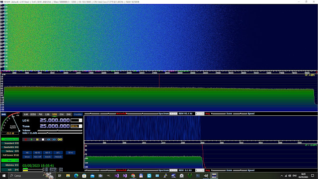
WGN240 - Another Gaussian white noise generator for HF use
One common approach is to use the sum of multiple LFSR sources to generate a random variable with a Gaussian distribution. The central limit theorem states that the sum of a large number of independent and identically distributed random variables (such as the outputs of independent LFSRs) tends towards a Gaussian distribution. But what is the Central Limit Theorem? by 3Blue1Brown
In this tentative design I used an Altera MAXII CPLD and an analog resistive adder.
Note that the resistor ladder circuit will produce binary values that are discrete , so the resulting Gaussian noise will also be discrete rather than continuous.
The central limit theorem states that the sum of a large number of independent and identically distributed random variables (such as the outputs of independent LFSRs) tends towards a Gaussian distribution. In practice, the number of LFSR sources required to achieve a good approximation of a Gaussian distribution depends on the size of the LFSRs and the desired level of accuracy.
Here 16 sources are used and the output dac integer value ranges from 0 to 16 with an approximation of a continuous Gaussian distribution.
It's important to note that generating Gaussian noise using LFSRs can only provide an approximation of the true Gaussian distribution, as the LFSRs generate a discrete set of values that are not perfectly random.
A cheap prototype board of EPM240 CPLD is used.
The code is written in Verilog https://github.com/ik1xpv/WGN240
The board has a 50 MHz clock running a synchronous machine consisting of 8 LFSRs.
LSFRs are Fibonacci type, and two outputs are taken from each.
16 independent sequences of binary data are obtained by combining two LSFR outputs from different LFSRs.
The linear combination of the two LSFRs is made with XOR, and the resulting period is the product of the two LSFR sequences when they are relatively prime
The 16 outputs are connected to an analog sum network consisting of 16 equal resistors of 800 Ohms. The output impedance results R/N = 800 /16 = 50 Ohms.
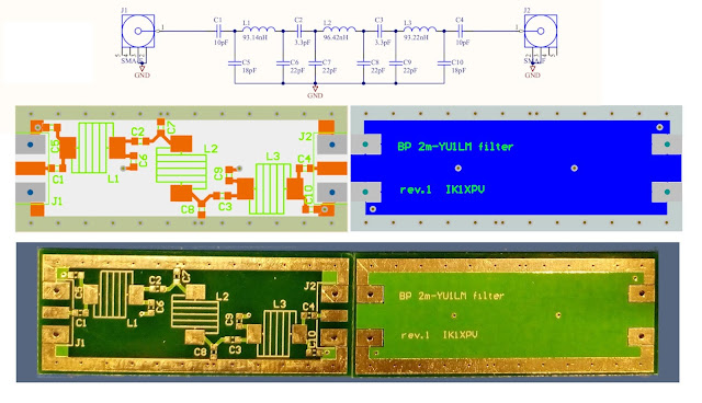
The generated signal ranges from 0 to 3.3V. So a capacitive high pass is made with a parallel of 10uF / 0.1uF / 10nF / 1nF / 100pF and the output will swing +/-1.65Vp.
The hardware is housed in a tin box with the 5Volt power socket and the SMA output.


Thanks for sharing this informative blog ! Looking for expert prototype engineering and development services? IDP is a leading prototyping company specializing in invention engineering. Get started!
ReplyDelete