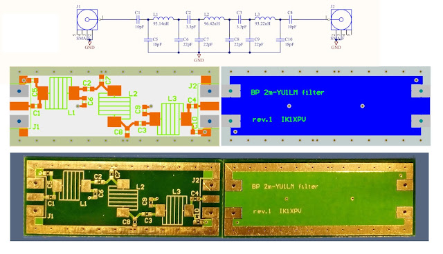
Filter in a box
In 2018 I read this paper Band Pass Filter with Low Insertion Loss for 2m by Dipl ing Tasić Siniša –Tasa YU1LM/QRP,
I made my PCB version for SMD components with a ground plane dimension of 50 x 20 mm so that a PCB of 10 x 10 cm houses 10 filter boards .
I mounted my first prototype with tin shield box and verified that the filter was fine in 2018. The point was that the spacing of the inductors' turns requires some instrumentation to do easily the tuning.The tin shielding soldered box I made was quite laborious for me.
So the pcbs has been unused for two years. I placed the PCB gerber files and scheme in
Now with the very nice SATSAGEN by Alberto IU1KVL the tuning of filter is fast and easy, see https://youtu.be/yjobY6vs4z0.
I used the 3D printer to make a PLA box to shield the filter https://www.thingiverse.com/thing:4787596/files
To design the inductors I use this calculator https://www.translatorscafe.com/unit-converter/en-US/calculator/coil-inductance/?D=5&Du=mm&l=5&lu=mm&N=5
To made the coil use a drill tip and an electric screw driver.
WARNING use gloves and pliers not to hurt yourself !
The shield is made wrapping the box with conductive copper tape, I bought it on https://www.aliexpress.com/premium/copper-tape-conductive-adhesive.html
Then I tested some different filters:
143-149 MHz BPF
This is the original design by YU1LM. I simulates it with LTspice. The tuning of the inductors was made using SATSAGEN and the PCB unboxed. Of course you decrease inductance spacing the turns a little...
On the left you can see the LTspice simulation with ideal components. The right image is the result measured using SATSAGEN. The measure is made with the shielded box. I imagine that Pluto hardware has some dynamic limit due to spurs and ADC resolution. https://www.youtube.com/watch?v=lC_hrQCHXaA&ab_channel=Adam9A4QV.
88-108 MHz BPF
Changing the components as in the following picture I made an FM band pass filter
This filter could be used in the front-end direct or under sampling FM SDR.
32 MHz LPF
Here I modified the scheme adding series resonance to made a LPF with FM band notch
The three added C5, C6, C7 capacitors are normal (non SMD) components.
These filter are quite cheap and relatively easy to assemble. The design can be improved with better SMD layout and adding the missing components' footprints.


Very nice filters!
ReplyDeleteCiao
Alberto
Thanks for sharing. Expects a lot more shares like this from your end. Few Months back, I'm looking for a band pass filter after too many search finally placed an order with the Anatech Electronics for all of my required band pass filters, as well as a request for a custom band pass filter design. Finally, I have got high quality band pass filter at the best price from them on time. If you're looking for a band pass filter, you can reach out them to obtain a high quality band pass filter.
ReplyDeleteThis is a good article on Band pass filter. As a electrical engineer any one can make this device based on this article. Thanks for sharing.
ReplyDeleteApple iPhone 13 Pro Max