Posts

Showing posts from September, 2020

The PC part of SDR receiver, a cheap solution

Image
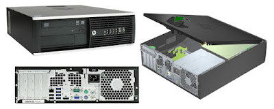
In the development of HF103 rc1 I used a dedicated PC and selected on Amazon an HP Elite 8300 SFF Small Form Factor Business Desktop Computer, Intel Quad-Core i7-3770 up to 3.9Ghz CPU, 8GB RAM, 256GB SSD , DVD, USB 3.0 , Windows 10 Professional (Renewed). It is a recycled PC !  I liked the SFF cover design as it allows you to open and close it very easily. This type of PC is used by Gamers who add an LP graphics card, I used it as it arrived without adding any card. Here a video shows the internals . I had no need to change the fans. It has the HP logo! I’ve been fond of HP since when I met HP instruments and documentation during my working days. See HP Origins - Hewlett Packard Documentary … my subconscious appreciates an SDR with HP logo... Minor mechanical defects may be there. I had to adjust the cover handle mechanism with my unit. I increased the ram to 16 GB as I had the memory sticks in my drawer and added a 1TB HDD to increase data storage space. After installing the Window

Measurement of noise figure of HF103 rc1

Image
     “ Fairly accurate comparative measurements may be made with HDSDR.  Please remember the method used, without reference to a suitably calibrated source measurements will not be absolute. But this method might provide an experimenter with a useful way of comparing equipment . “   Source:    Signal Measurement with HDSDR   Thanks to the HDSDR Authors and to G4ZFQ. My RF reference is a 14 pin metallic dip crystal oscillator at 20MHz with sine wave output. It’s output is 400 mVpp sine wave on 50 Ohm resistor. I placed a  20dB attenuator at the output so that the reference on a 50 Ohm load is  40mVpp,  -24dBm.  I measured the levels with an Hantek Oscilloscope.   The procedure to measure NF is as follow: - Connect the reference generator to HF103 antenna input and run the HDSDR application. - Set RFgain to 0dB attenuation. - Select the Smeter to rms mode (click with the mouse on peak/rms indication to toggle mode). This is important as peek/rms ratio is different for sinewave or noise.

HF103 rc1

Image
HF103 is a HF only prototype of BBRF103  that started at the end of 2019. Thanks to Andrew G4XZL for ideas, test reports and advice.  Here after the modifications. Hardware: - It is designed for LW-MW-HF band only: 0-30MHz. - A Low Noise Amplifies has been added to improve NF of receiver. - The Clock reference used is a low noise xtal oscillator with lower phase noise and spurs than Si5351a.     - The RF attenuator of HF103 uses  DAT-31-SP+   - The PCB has been made larger 100x100 mm to increase spatial separation between components' groups (COVID style)  Here the  scheme and PCB layout . Some pictures of hardware Case  ADC and RF layout                                                                       LNA, filter, attenuator and xtal oscillator Software (still in evolution) : - The reference clock oscillator, that is the ADC sampling frequency has accuracy error. The error is compensated with a software trimming value into the ExtIO.dll's user interface dialog. - The ExtI