Measurement of noise figure of HF103 rc1

“Fairly accurate comparative measurements may be made with HDSDR. Please remember the method used, without reference to a suitably calibrated source measurements will not be absolute. But this method might provide an experimenter with a useful way of comparing equipment. “
Source: Signal Measurement with HDSDR Thanks to the HDSDR Authors and to G4ZFQ.
My RF reference is a 14 pin metallic dip crystal oscillator at 20MHz with sine wave output. It’s output is 400 mVpp sine wave on 50 Ohm resistor. I placed a 20dB attenuator at the output so that the reference on a 50 Ohm load is 40mVpp, -24dBm. I measured the levels with an Hantek Oscilloscope.
The procedure to measure NF is as follow:
- Connect the reference generator to HF103 antenna input and run the HDSDR application.
- Set RFgain to 0dB attenuation.
- Select the Smeter to rms mode (click with the mouse on peak/rms indication to toggle mode). This is important as peek/rms ratio is different for sinewave or noise. We need rms to measure NF.
- Select USB demodulator. I used a 3 kHz bandwidth filter.
- Tune to generator carrier and measure the tone level with the S-meter; verify that it is the expected value. In case adjust calibration gain to read the generator level ( mine is -24 dBm ),

- Move to a clean frequency one MHz up or disconnect the generator and terminate the antenna on 50 Ohm.
- Measure the S-meter level of the noise signal with 3kHz bandwidth. My measure is -125 dBm

- Now we can compute the thermal noise component on 3kHz
at 20°c of a 50 Ohm
K = Boltzmann's constant = 1.381 × 10⁻²³W/Hz/K,
T = 290 K at room temperature
B = Bandwith
KTB for B 1Hz = -174 dBm at room temperature.
KTB for B 3000Hz = -174 + 10 log( 3000 ) = - 139 dBm
The estimated NF value based on HF103 scheme is:
( I use https://www.everythingrf.com/rf-calculators/cascaded-noise-figure-gain-calculator)
Stage NF(dB) Gain(dB) Note /source
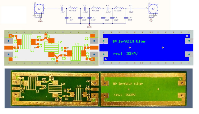
1 0.1 -0,1 Insertion loss 1st filter estimated value
2 1.3 -1.3 DAT-31A-SP+ datasheet typ value
3 0.2 -0.2 Insertion loss 2nd filter estimated value
4 6.2 20 LTC6400-20 datasheet typ value
5 30,7 Soft. value LTC2208 see High speed ADC: one that no one had ever told you
( see: ADC Noise Figure—An Often Misunderstood and Misinterpreted Specification by Walt Kester )
NF 13.63 Preview NF based on estimated components noise figure
The estimated and the measured are within the error margin.
Here the noise level with no antenna connected.


Comments
Post a Comment