fl2k_noise generator
The osmo-fl2k project shows how to use an USB 3.0 VGA adapter as SDR transmitter.
Many thanks to Steve Markgraf. He presented it at OsmoDefCon 2018 https://youtu.be/VRvLVjLQSaw .
I made a console tool named fl2k_noise that generates white noise in the full HF band.
Many thanks to Steve Markgraf. He presented it at OsmoDefCon 2018 https://youtu.be/VRvLVjLQSaw .
I made a console tool named fl2k_noise that generates white noise in the full HF band.

You can buy Fresco Logic 2000 based USB to VGA adapter in Aliexpress or Ebay for some 5-10$ price.
See more info and the adapter scheme on https://gitlab.hamburg.ccc.de/MarBle/fl2k-liberation/tree/assets
The adapter was laying in my shack when I decided to test it as wide band (white) noise generator for HF band.
I selected an old VGA to VGA cable quite long and flexible and I cut it in the middle,
I cabled it as in the following scheme to adapt the 3 *75 Ohm input to the 50 Ohm output.
The capacitors remove the VGA DC component and in case isolates the ANT bias tee of the receiver.

The tentative code is in my repository https://github.com/ik1xpv/fl2k_win . It's a fork from https://github.com/winterrace/fl2k_win that added windows project files to
the original http://git.osmocom.org/osmo-fl2k.
The source for the noise is in the file https://github.com/ik1xpv/fl2k_win/blob/master/src/fl2k_noise.c
A linear shift register 64 bit long generates the noise sequence.
uint64_t lfbsr(uint64_t* i, uint64_t* fb)
{
if (*i & 1) { *i = (*i >> 1) ^ *fb; }
else { *i = (*i >> 1); }
return *i;
}
uint64_t r0 = 0x1234567890123456ULL;
uint64_t fb0 = 0x800000000000057CULL; // 64 bit max lem see https://users.ece.cmu.edu/~koopman/lfsr/
In a first test I used a separate lfsr for every dac channel RGB.
At the end I'm using a single stream equal and in phase for all the three output.
In this way we have a uniform distributed amplitude samples. It is not Gaussian distributed amplitude
but it is wide band (white) and it has a higher rms and it is amplitude limited to the dac 8 bit range.
The DACs' tx buffer is modified in the main while loop asynchronously.
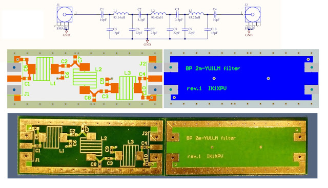
Here an analysis of a simple (2 xtal ?) filter

While this one is more sharp and uses more (8 ?) xtals.

Please notice that I connected the generator and receiver directly with 50 Ohm in/out; this enhance the filter in band ripple. An adapting impedance network as a transformer is required to get the real performance of filter.
Here a single 4.228 MHz Xtal.

The program CPU load is not very high:

The noise performance of FL2000 based adapter is limited by the 8 bit DACs and the board 2 layers pcb with a switching regulator. That is not a big issue when we use it as noise source.


Can you explain idea behind 75 to 50 ohm "converter"? BEcause at a first glance I cannot see logic.Also due to phase difference between RGB there can appear "not-clear-noise"?
ReplyDeleteThe vga cable uses three inner coax cable 75 Ohm impedance. The resistive network terminates each one to 75 ohm keeping the cable response flat in frequency while the output generator impedance results 50 Ohm .
ReplyDeleteIn a first test I used three different lfsr, a separate lfsr for every dac channel (RGB).
The output sequences of lfsrs are then uncorrelated and when summing together partially cancel each other as they are not in phase. While generating the three output from a single lfsr they are equals and sum together increasing the output level.
Molto grazie per rispondere. Even if you use one lfsr , on low level (assembler instruction) there will be delay because registers and/or memories cannot be accessed strictly simultaneously, but sequentially with delay much smaller than with 3 different lfsr,but still delay. HAve you seen 3 channels on 3 channel oscilloscope in order to be sure that there are no even small phase noise (phase difference between 3 channels)? I personally can imaging how on SERIAL USB device there can be simultaneous, synchronous output to 3 channels. Even more, as original fl2k SDR source claimed that maximal output is limited differently on different PC host USB boards.Max on Intel board(south bridge), min on Renaissance/NEC uPD board . How can be generated on all 3 channels in same lfsr? i see the source, but....
DeleteThank you! I've had some ideas to use the FL2K as a transmitter for weak signal modes. It obviously needs filtering and I wanted to make a noise generator to test out some designs (and compare the results to my nanoVNA).
ReplyDelete